● Free course · Agile QS Academy

AgileBOQ from zero to hero

A complete, step-by-step course for quantity surveyors, estimators and students anywhere in the world. Start with the screen, finish by measuring, pricing and programming a whole house from its drawing, and check your numbers against our answer key.

16modules in 4 levels
≈ 10 hincluding the capstone
48quiz questions with answers
48items in the capstone answer key
Your progress
0 of 17 complete · saved in this browser

Learning path

Work through the levels in order. Each module has a goal, the steps exactly as they appear on screen, pro tips, a common mistake to avoid, an exercise and a three-question check.

Level 1 · Start

Learn the screen, set up a project and bring in your drawings.

  1. 01Welcome and screen tour
  2. 02Accounts, projects and saving
  3. 03Project set-up in Settings
  4. 04Drawings: import, scale and align

Level 2 · Model

Build every element of a building, from footings to fittings.

  1. 05Drawing tools and precision
  2. 06Substructure
  3. 07Frame, floors, stairs and structural schedules
  4. 08Walls, openings, roofs and finishes
  5. 09MEP and external works
  6. 10Steel frames and composite items

Level 3 · Report & price

Check the model, then turn it into priced, programmed documents.

  1. 11Check the model
  2. 12Reports and exports
  3. 13Pricing
  4. 14Programme 4D and cash flow

Level 4 · Hero

Work fast with automation, work as a team, and prove it on a full project.

  1. 15Automate BOQ and IFC import
  2. 16Working as a team
  3. ★Capstone: Practice House A
Level 1 · StartModule 0120 min

Welcome and screen tour

Know where everything is, so every later lesson is only about quantities.

You will learn
  • What AgileBOQ does and what it produces
  • The six parts of the screen
  • How to open the sample project and move around it

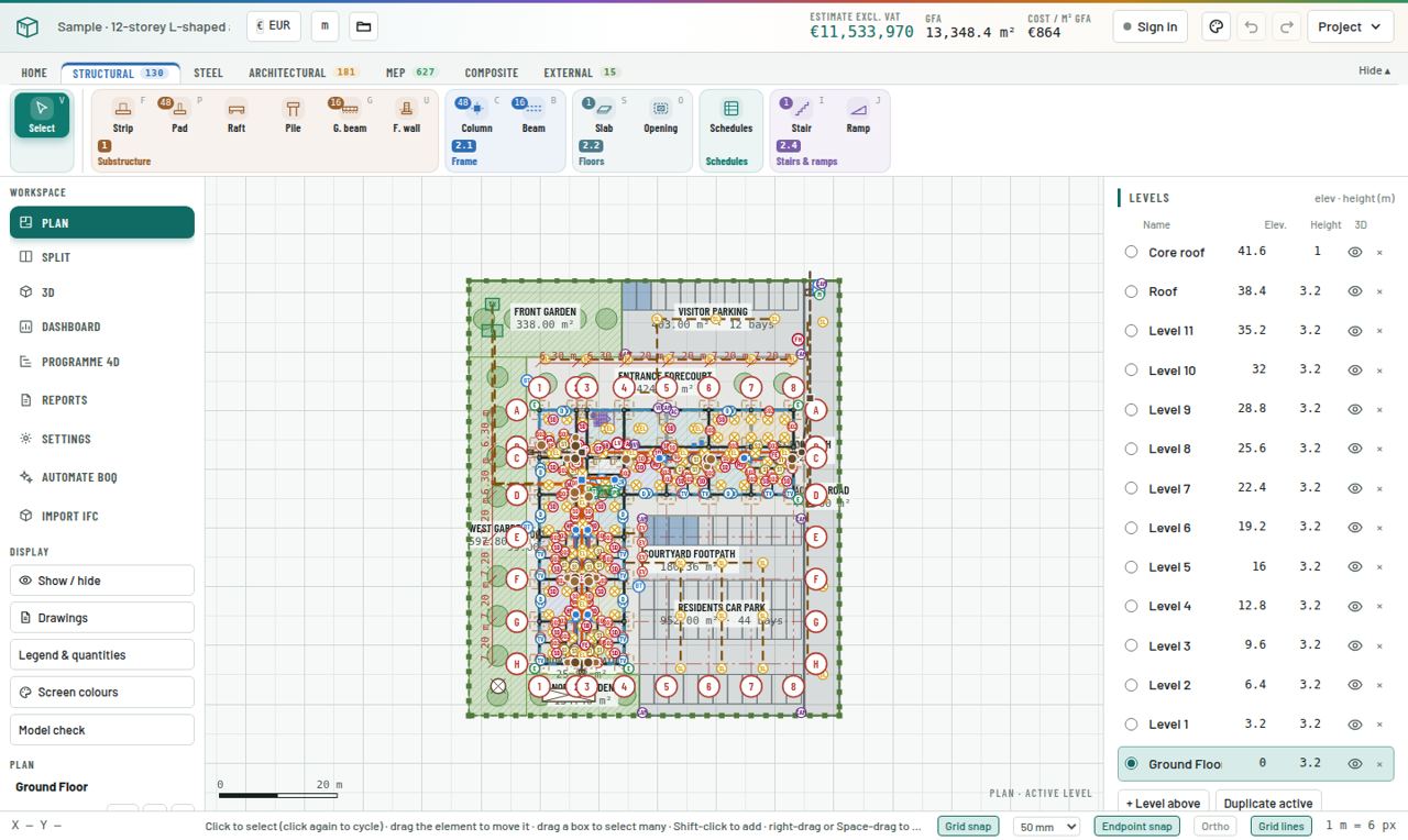
Split view of the sample 12-storey apartment block: ribbon at the top, workspace menu on the left, plan and 3D in the middle, levels and properties on the right.
Step by step
  1. Open the app

    Go to www.agileboq.com and click Open the app. It runs in any modern browser on Windows, Mac or Linux. Nothing to install.

  2. Read the top bar

    Left to right: project name, currency, units, project folder. In the middle, the live Estimate excl. VAT, GFA and Cost / m² GFA. These update every time you draw or change an element. On the right: Sign in, Screen colours, Undo, Redo and the Project menu.

  3. Learn the ribbon tabs

    Under the top bar are the ribbon tabs: Home, Structural, Steel, Architectural, MEP, Composite, External. Each tab holds the drawing tools for that discipline. The small number on a tab is how many elements of that discipline are in the model. Double-click a tab to hide the ribbon and give the drawing more room.

  4. Use the Workspace menu

    The left menu switches what you see: Plan, Split (plan and 3D side by side), 3D, Dashboard, Programme 4D, Reports and Settings, plus Automate BOQ and Import IFC. Below it, the Display tools: Show / hide, Drawings, Legend & quantities, Screen colours and Model check.

  5. Find the right-hand panel

    Levels sits at the top: each floor with its elevation and height. The active level (filled dot) is the one you draw on. Below it, Selection shows the properties and quantities of whatever you click.

  6. Check the status bar

    At the bottom: cursor coordinates, a hint for the current tool, and the snap switches Grid snap, grid step, Endpoint snap, Ortho and Grid lines.

  7. Open the sample

    Open the Project menu and choose Load sample apartment block. You now have a complete 12-storey building to explore without breaking anything of your own.

Pro tips
  • Press the Split view while you learn. Every click on the plan is immediately visible in 3D.
  • Hover any ribbon button to see its name and keyboard shortcut.
Common mistake
  • Drawing on the wrong floor. Always glance at the active level before you draw.
Exercise

Open the sample. Find (1) the total estimate, (2) the number of MEP elements, (3) the elevation of Level 5. Switch to 3D and orbit round the building.
Check yourself · 3 questions
1. Where do you see the live estimate while you model?
2. Which view shows plan and 3D side by side?
3. What does the number on a ribbon tab mean?
Level 1 · StartModule 0220 min

Accounts, projects and saving

Create, save, reopen and back up projects safely.

You will learn
  • Guest view versus signed-in editing
  • Creating a new project and choosing the country
  • Where projects are saved and how to back them up
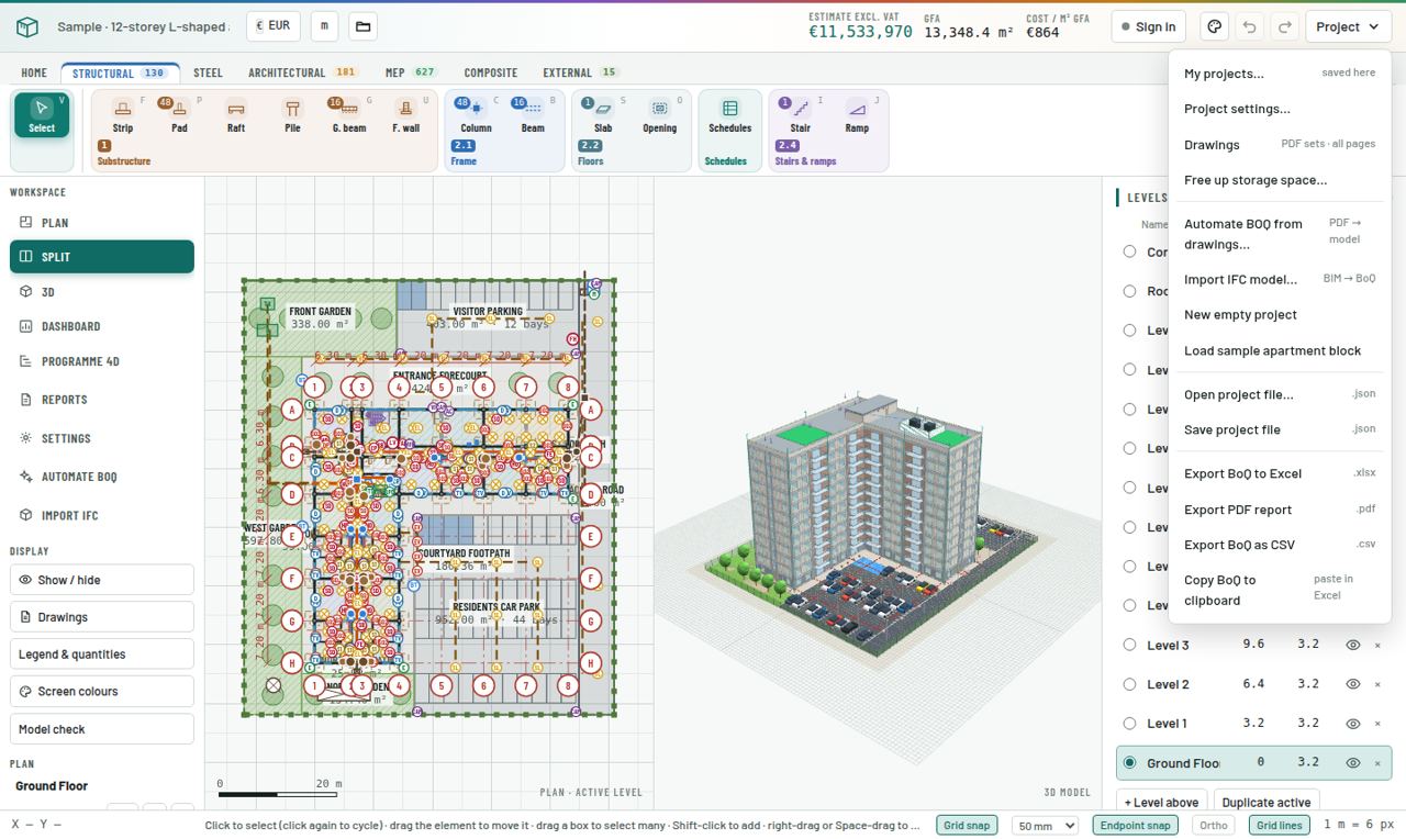
The Project menu with My projects, Project settings, Drawings, Automate BOQ, Import IFC, New empty project, sample, open and save, and exports.
Step by step
  1. Understand guest view

    Without an account you can open and look at models, including the sample, in view-only mode. To draw, edit or save you need a free account.

  2. Sign in

    Click Sign in in the top bar and create a free account with your email. Once signed in, the view-only bar disappears and all tools unlock.

  3. Start a new project

    Open Project → New empty project. Choose the country first: it sets the currency and loads that country's price database, so rates are sensible from the first element.

  4. Name it

    Go to Settings → Project & currency and give the project its real name and reference. The name appears on the cover page and in every export.

  5. Find your projects

    Project → My projects… (or the folder button in the top bar) lists your saved projects. Open one to continue where you left off.

  6. Back up a copy

    Project → Save project file downloads a .agileboq.json file. Keep it with the job records. Open project file… loads it again on any computer.

  7. Keep storage tidy

    Large PDF drawing sets use browser storage. Project → Free up storage space… shows what is stored and lets you remove what you no longer need.

Pro tips
  • Save a project file at each milestone (tender, revision A, revision B). It is your audit trail.
  • Use Undo (Ctrl+Z) and Redo (Ctrl+Y) freely. Every change is recorded.
Common mistake
  • Choosing the wrong country. Rates and currency follow it. You can change it in Settings, but check the rates after you do.
Exercise

Sign in, create a new empty project for your own country called "Training – [your name]", then save a project file to your computer.

Check yourself · 3 questions
1. What can a guest do without signing in?
2. What does the country choice set?
3. How do you keep an offline backup of a project?
Level 1 · StartModule 0330 min

Project set-up in Settings

Set levels, grids, site data and measurement rules before drawing, so quantities come out right first time.

You will learn
  • Levels and floor heights
  • Structural grid lines
  • Site and substructure data
  • Measurement rules and concrete mixes
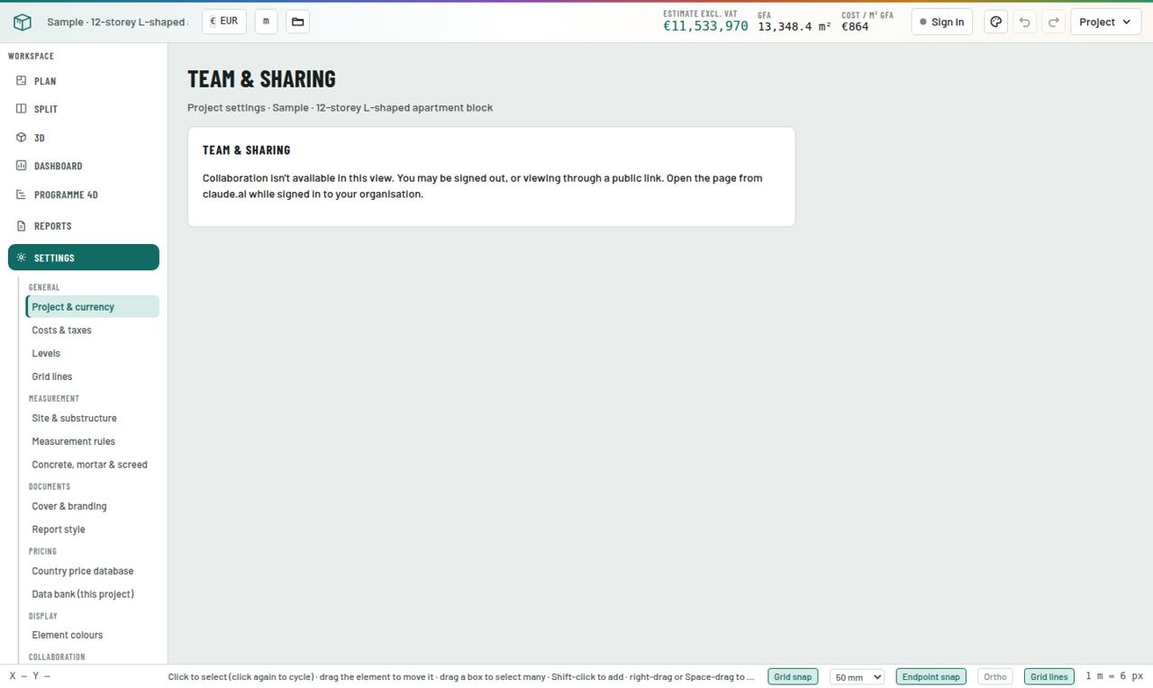
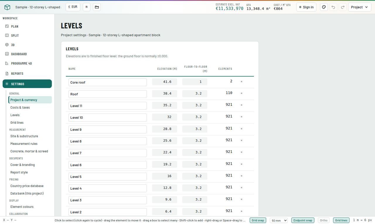
Settings → Levels with each floor, its elevation and floor-to-floor height.
Step by step
  1. Open Settings

    Click Settings in the Workspace menu. The left list is grouped: General, Measurement, Documents, Pricing, Display, Collaboration.

  2. Set the levels

    General → Levels: name every floor and give its elevation and height. Or use + Level above and Duplicate active in the right-hand Levels panel. Wall and column heights follow the level height unless you override them.

  3. Set the grid

    General → Grid lines: enter grid spacings to generate the structural grid (1, 2, 3… and A, B, C…). Elements snap to grid intersections, and structural schedules use the grid names as locations.

  4. Enter site data

    Measurement → Site & substructure: existing ground level, topsoil strip, hardcore bed, working space, earthwork support, anti-termite treatment, disposal. These drive every excavation and ground-floor item.

  5. Check measurement rules

    Measurement → Measurement rules: how openings are deducted, how internal finishes are measured, and similar NRM2 conventions. Leave the defaults unless your client's method says otherwise.

  6. Check the mixes

    Measurement → Concrete, mortar & screed: cement, sand and aggregate per m³ for each grade. The Bill of Materials uses these.

  7. Set costs and taxes

    General → Costs & taxes: preliminaries %, contingency %, VAT %. These sit on top of the measured work in the summary.

Pro tips
  • Set levels before you draw anything. Moving a level later moves every element on it, which is correct, but it is quicker to get it right first.
  • Negative existing ground level (for example −0.30) means the site is below finished floor level. Fill quantities follow from this.
Common mistake
  • Leaving the default 3.0 m floor height when the drawings say 3.2 m. Every wall and column is then 6% short.
Exercise

In your training project, create Ground Floor at 0.00 (3.0 m high) and Roof at 3.00. Set existing ground level to −0.30 and topsoil strip to 0.15 m.

Check yourself · 3 questions
1. Where do you enter topsoil strip and hardcore thickness?
2. Which report uses the concrete mix settings?
3. Why set the grid early?
Level 1 · StartModule 0425 min

Drawings: import, scale and align

Put your PDF drawings under the right levels at the correct scale, ready to trace.

You will learn
  • Importing PDF and image drawings
  • Putting pages under levels
  • Calibrating scale on a known dimension
  • Aligning the drawing to the grid
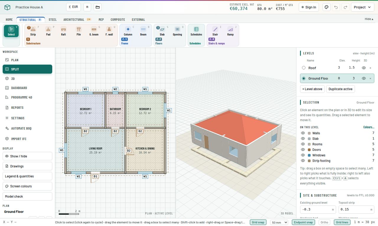
The practice house traced over its drawing, shown on plan and in 3D.
Step by step
  1. Import

    Click Drawings in the Display menu (or Project → Drawings) and add your PDF set or images. Every page is kept with the project.

  2. Place pages under levels

    For each page choose Put this page under the active level. For a set that is in floor order, use the option that puts page 1 under the lowest level, page 2 under the next, and so on.

  3. Calibrate the scale

    On the Home tab choose Calibrate drawing scale (K). Click both ends of a dimension you know, for example the 10.0 m overall dimension, then type its real length. Always calibrate on the longest dimension you can find: small errors shrink.

  4. Check the scale

    Use Measure distance (M) on a second dimension. If it reads correctly, the scale is right.

  5. Align

    Move drawing underlay: click a point on the drawing (a grid intersection), then click where that point should sit in the model. Do this on every level so floors stack exactly.

Pro tips
  • Calibrate each page separately. Sheets in the same set are not always printed at the same scale.
  • Use Screen colours to fade the drawing or change the background when lines are hard to see.
Common mistake
  • Calibrating on a short dimension such as a door width. A 1 mm click error on 0.9 m is 0.1%; on 10 m it is 0.01%.
Exercise

Download the Practice House A drawing (Capstone section). Import it under Ground Floor, calibrate on the 10 m dimension, then measure the 8 m dimension to check.

Check yourself · 3 questions
1. Which dimension is best for calibrating?
2. How do you check the scale after calibrating?
3. What does Move drawing underlay do?
Level 2 · ModelModule 0520 min

Drawing tools and precision

Draw quickly and exactly, and edit without redrawing.

You will learn
  • The four ways tools place elements
  • Typing exact lengths
  • Snaps and ortho
  • Selecting, moving and deleting
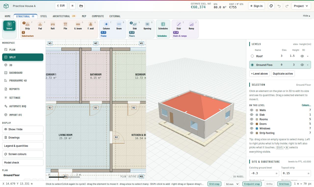
Plan view with snaps, grid lines and the tool hint in the status bar.
Step by step
  1. Know the four tool types

    Point tools (column, pad, pile, sanitary fitting, manhole) place with one click. Chain tools (wall, beam, strip, pipe, cable, fence) click from point to point. Polygon tools (slab, roof, raft, paving) click each corner and close. Opening tools (door, window, louvre) click on a wall.

  2. Draw a chain

    Click to start, click each next point. Esc or right-click stops. Hold Shift for ortho.

  3. Type exact lengths

    After the first click, move the cursor in the direction you want, type a length in metres (for example 4.5) and press Enter. The point is placed exactly 4.5 m along the cursor direction.

  4. Close a polygon

    Click each corner, then click the first point again or press Enter.

  5. Use snaps

    Endpoint snap locks onto wall ends and corners. Grid snap uses the grid step (10, 50, 100 or 500 mm). Grid lines snaps to the structural grid and its intersections.

  6. Select and edit

    Press V for Select. Click an element to select it (click again to cycle through overlapping ones). Drag to move. Drag a box to select many: left-to-right picks what is fully inside, right-to-left also picks what it touches. Shift-click adds. Ctrl+A selects everything visible. Del deletes.

  7. Edit properties

    With an element selected, change its size, material, reinforcement and mark in the right-hand panel. With several selected, the change applies to all of them.

  8. Navigate

    Wheel to zoom, right-drag or Space-drag to pan, Home to fit.

Pro tips
  • Learn the shortcut letters: W wall, C column, B beam, S slab, R room, D door, N window, T roof, F strip, P pad. They double your speed.
  • Select many similar elements and edit them together rather than one by one.
Common mistake
  • Walls that nearly meet. Endpoint snap must be on, otherwise corners overlap or leave gaps, and Model check will flag them.
Exercise

In a blank project, draw a 10 × 8 m rectangle of walls using only typed lengths, then select all four walls and change them to 200 mm blockwork in one go.

Check yourself · 3 questions
1. How do you place a wall point exactly 4.5 m from the last one?
2. A right-to-left selection box picks…
3. Which key finishes a wall chain?
Level 2 · ModelModule 0640 min

Substructure

Model foundations so excavation, concrete, formwork and reinforcement are measured to NRM2.

You will learn
  • Strip, pad, raft and pile foundations
  • Ground beams and foundation walls
  • Reinforcement on footings
  • Checking excavation items
The Structural tab with the Substructure tools (Strip, Pad, Raft, Pile, G. beam, F. wall), and Practice House A with its strip footings in 3D.
Step by step
  1. Choose the tool

    On the Structural tab, Substructure group: Strip (F), Pad (P), Raft, Pile, G. beam (G) and F. wall (U).

  2. Strip footings

    Draw along wall centrelines like a wall. In the properties set width, depth, concrete grade, excavation depth, main bars and distribution bars.

  3. Pad footings

    Click each column position. Set plan size, depth, plain or stepped shape, excavation depth, stub column and bar sizes and spacing. Give each a mark (F1, F2…).

  4. Rafts and piles

    A raft is a polygon with thickness, thickenings and top and bottom mesh or bars. A pile is a point with diameter, length, number in the group and cap size.

  5. Ground beams and foundation walls

    Chain tools between pads or along the perimeter. They carry their own size, formwork and reinforcement.

  6. Read the result

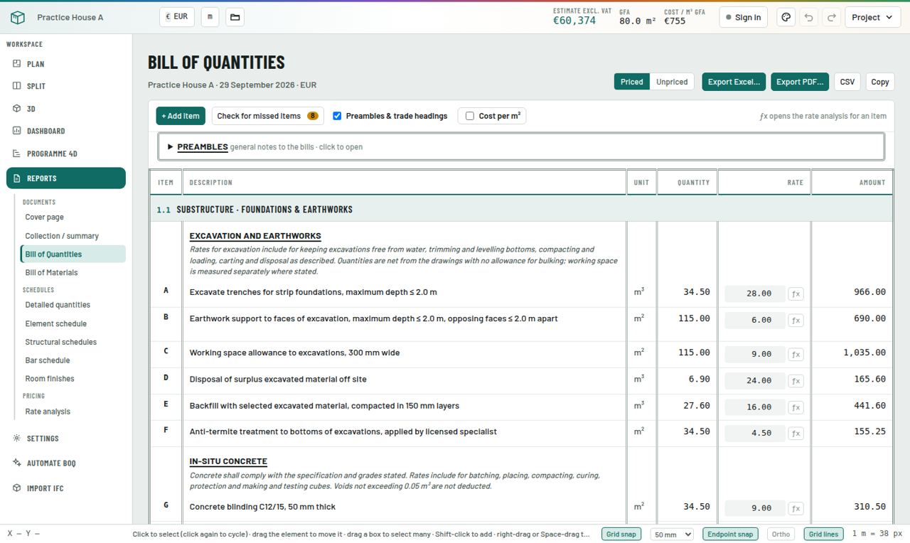
    Open Reports → Bill of Quantities, section 1.1. You will see excavation, earthwork support, working space, disposal, backfill, blinding, concrete, formwork, reinforcement by diameter and damp-proof course, all generated from what you drew.

  7. See the steel

    In the 3D panel, Footing reinforcement in 3D draws every pad and strip bar on the active level, bar by bar.

Pro tips
  • Select a finished pad and click Duplicate in the Selection panel, then drag the copy into place, instead of re-entering its properties for every column.
  • The Site & substructure settings (Module 3) decide working space and earthwork support. Check them before you trust excavation quantities.
Common mistake
  • Drawing strip footings at the wall face instead of the centreline. Concrete is right but trench lengths at corners are wrong.
Exercise

Trace strip footings under every wall of Practice House A: 600 × 200 mm, C25/30, trench 1.0 m deep. Check that section 1.1 shows about 6.9 m³ of foundation concrete.

Check yourself · 3 questions
1. Where do strip footings get drawn?
2. Which view draws footing bars one by one?
3. Where does working space allowance come from?
Level 2 · ModelModule 0745 min

Frame, floors, stairs and structural schedules

Model columns, beams, slabs and stairs, or generate them from your structural schedules.

You will learn
  • Columns and beams with reinforcement
  • Slabs, openings and levels
  • Stairs and ramps
  • Importing schedules and generating the frame
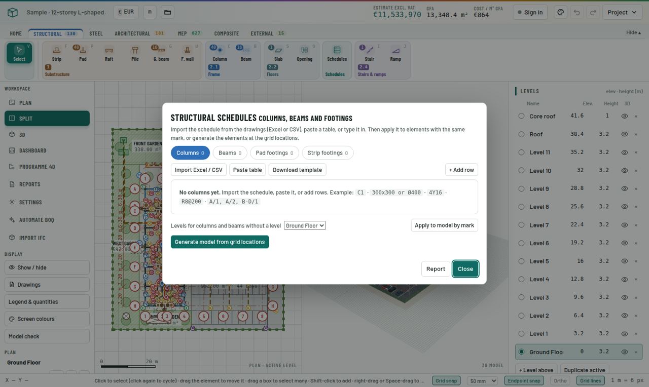
Structural schedules dialog: columns, beams and footings imported from a schedule and applied to marks.
Step by step
  1. Columns

    Tool Column (C): click each position, ideally on grid intersections. Set shape (rectangular or circular), size, main bars, links and cover. RC columns take their height from the level.

  2. Beams

    Tool Beam (B): chain from column to column. Set width, depth, top and bottom bars, links and spacing.

  3. Slabs

    Tool Slab (S): click each corner of the slab edge. Set thickness, mesh or bar reinforcement and edge details. Use Opening (O) for stair wells and shafts; they are deducted automatically.

  4. Repeat floors

    When a floor is complete, make it the active level and click Duplicate active in the Levels panel. It adds a new level on top and copies every element of the floor to it, except foundations, ground beams and external works. Then change only what differs.

  5. Stairs and ramps

    Stair (I) and Ramp (J) are chains along the walking line. Set width, risers, goings, waist and landings.

  6. Import a schedule

    Click Schedules on the Structural tab. Upload the engineer's column, beam, pad or strip schedule as Excel or CSV, or paste it. Columns such as Mark, Size, Main bars, Links and Grid locations are recognised automatically. Download the template if your schedule is laid out differently.

  7. Apply or generate

    Apply to marks updates every element that already carries that mark (C1, B3, F2…). Generate model from grid locations creates the elements at the grid positions in the schedule (for example A/1-5).

  8. Report it

    Reports → Structural schedules lists every scheduled member with its count, concrete and steel, and flags any mark that is not modelled.

Pro tips
  • Put marks on everything (C1, B1, F1). Marks connect the model to schedules, bar schedules and reports.
  • For a tall building, model one typical floor fully, check it, then duplicate.
Common mistake
  • Forgetting slab openings for stairs and lift shafts: concrete and formwork are then overstated.
Exercise

Open the sample. Open Schedules, look at the imported column schedule, then open Reports → Structural schedules and find the total steel weight for columns.

Check yourself · 3 questions
1. What does "Apply to marks" do?
2. Which file types can a schedule be imported from?
3. How are stair-well openings handled?
Level 2 · ModelModule 0845 min

Walls, openings, roofs and finishes

Model the architecture so masonry, openings, roofing and room finishes are complete.

You will learn
  • External and internal walls
  • Doors, windows, louvres and curtain walls
  • Pitched and flat roofs
  • Rooms and finishes
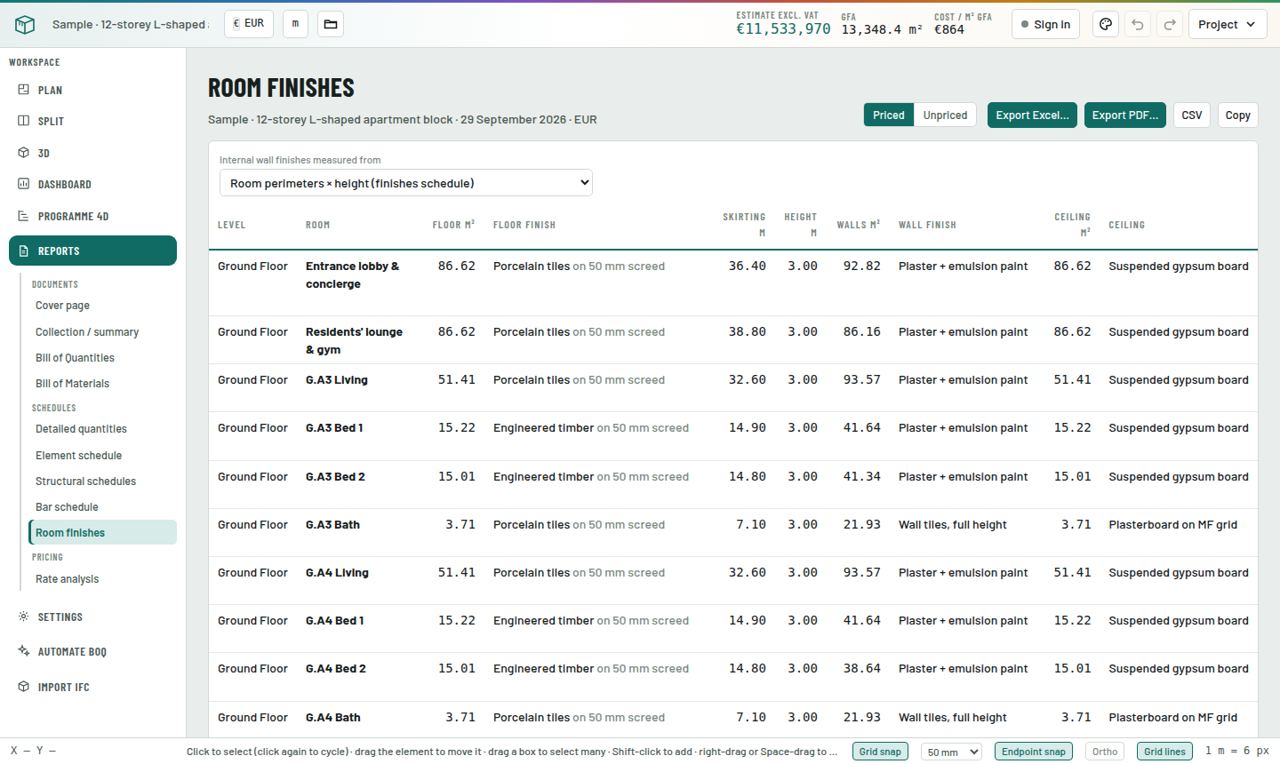
Room finishes schedule: floor, skirting, wall and ceiling finishes per room with areas.
Step by step
  1. Walls

    On the Architectural tab choose Wall (W). Set type (external or internal), material (blockwork, brick, stone, concrete, drywall), thickness and finishes before drawing. Draw on centrelines.

  2. Doors and windows

    Door (D), Window (N) and Louvre (Z): click on a wall where the opening goes. Set width, height, sill and mark (D1, W1). The opening is deducted from the wall and its finishes, and a lintel is added.

  3. Curtain walls

    Curtain wall (Q) is a chain with panel and mullion sizes.

  4. Roofs

    Roof (T): draw the roof outline (usually the wall line) on the roof level. Choose pitched tiles, sheeting or flat membrane; gable or hip; pitch; eaves overhang; and structure (timber trusses, steel). Trusses, ridge, hips, fascia, gutters, wall plate and straps are all measured.

  5. Rooms and finishes

    Room (R): click inside a space enclosed by walls. The outline follows the wall faces, and doors and windows on its perimeter are found automatically. Name the room and pick floor, screed, skirting, wall and ceiling finishes.

  6. Balustrades

    Balustrade / handrail (Y) for stairs, balconies and roof edges.

  7. Check

    Reports → Room finishes lists every room with its areas; the Bill of Quantities groups walls, openings, roof and finishes into their NRM sections.

Pro tips
  • Set the wall type before you draw. External walls get render and external paint; internal walls get plaster both sides.
  • Place rooms last, after all walls and openings, so their outlines and deductions are correct.
Common mistake
  • Drawing a roof on the Ground Floor level. Put it on the roof level so it sits on top of the walls.
Exercise

Complete the walls, doors (D1, D2), windows (W1, W2), hip roof and five rooms of Practice House A.

Check yourself · 3 questions
1. What happens when you place a window on a wall?
2. How do you create a room?
3. Which level should a roof be drawn on?
Level 2 · ModelModule 0935 min

MEP and external works

Measure plumbing, drainage, electrical points and site works.

You will learn
  • Sanitary fittings, pipes, fittings and manholes
  • Electrical points and cable runs
  • Fences, paving, parking and landscaping
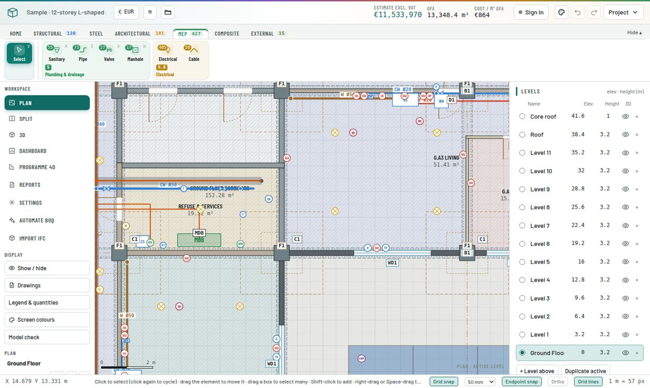
The MEP tab with Sanitary, Pipe, Valve, Manhole, Electrical and Cable tools, over a sample floor with pipe runs and electrical points.
Step by step
  1. Sanitary fittings

    MEP tab → Sanitary fitting (A): click to place WCs, basins, sinks, showers. Each carries its own supply and waste connections.

  2. Pipe runs

    Pipe run (E): chain along the route. Choose the system (cold water, hot water, waste, soil, rainwater, fire, gas and more), material and diameter. Colours follow the system legend.

  3. Fittings and chambers

    Valve / pipe fitting (X) and Manhole / drainage chamber (H) with depth, size and cover grade.

  4. Electrical

    Electrical point / equipment: lighting, switches, sockets, data, fire alarm, security, distribution boards. Each point includes its final circuit wiring from the board. Cable / containment run for trays, trunking and sub-mains.

  5. External works

    External tab: Fence / boundary wall (chain, with gates) and Paving, parking & landscaping (polygon: paving, asphalt, parking bays, grass, planting, kerbs).

Pro tips
  • Use Show / hide to switch off structure while you trace services, so the plan stays readable.
Common mistake
  • Counting pipe fittings by hand. Pipe runs generate bends and tees from their geometry; add fittings only for valves and special items.
Exercise

In Practice House A, add a WC, basin and shower in the bathroom, a sink in the kitchen, and a waste pipe to a manhole 3 m outside the rear wall.

Check yourself · 3 questions
1. Which tool measures a drainage chamber?
2. What is included with an electrical point?
3. Which tab holds fences and paving?
Level 2 · ModelModule 1035 min

Steel frames and composite items

Measure steel structures and self-contained items like tanks, septic tanks, pools and channels in minutes.

You will learn
  • Steel columns, beams and members
  • Generating a portal-frame shed
  • Tanks, septic tanks, pools and drainage channels
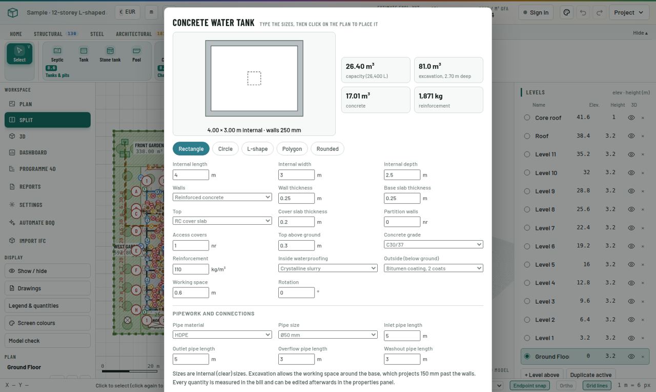
Composite designer for a concrete water tank: shape, dimensions, walls, cover, pipework and waterproofing, with a live preview.
Step by step
  1. Steel members

    Steel tab: Steel column (UC, HEB, SHS…), Steel beam (UB, IPE, HEA…) and Steel member for rafters, purlins, rails and bracing. Weights come from the section tables; coatings and fire protection are measured by area.

  2. Portal frame

    Portal frame builds a whole steel shed from two corners: frames, rafters, purlins, rails, bracing, base plates and cladding. Adjust bay spacing and sections afterwards.

  3. Open the designer

    Composite tab: Septic tank, Concrete water tank, Stone masonry water tank, Swimming pool and Drainage channel. Each opens a designer.

  4. Fill in dimensions

    Pick the shape (rectangle, circle, L-shape, polygon, stadium), type the dimensions, wall and base thickness, number of chambers, cover type and pipework. The preview and the quantities update as you type.

  5. Place it

    Click on the plan where the centre goes. Channels are chains: click the start, each change of direction, then double-click or Esc.

  6. Read it

    Composite items bill under their own headings (excavation, concrete, formwork, reinforcement, waterproofing, covers, pipework, testing), so a tank never gets lost in the general items.

Pro tips
  • Water tanks always include waterproofing, a water test and disinfection. Check the waterproofing system matches your specification.
Common mistake
  • Leaving the channel cover type on the default. Open, slab-covered and grated channels are priced very differently.
Exercise

Add a 3-chamber septic tank and a 10 m³ circular concrete water tank to Practice House A. Find both in the Bill of Quantities.

Check yourself · 3 questions
1. What does the Portal frame tool build?
2. How do you change a tank's shape?
3. Which items are always included for a water tank?
Level 3 · Report & priceModule 1125 min

Check the model

Catch mistakes before they reach the bill.

You will learn
  • 3D, sections and preset views
  • Legend & quantities
  • Model check
  • The Dashboard
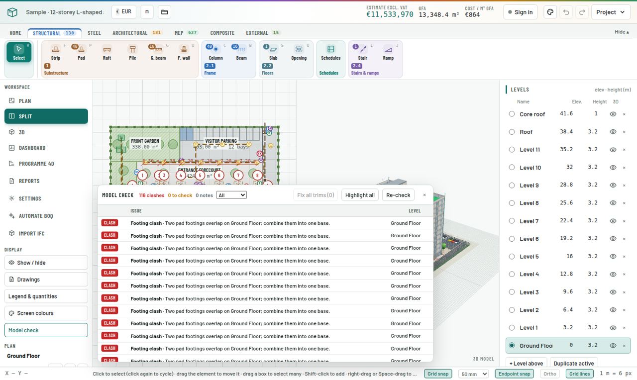
Model check listing clashes, overshooting walls and unsupported elements, each with its level.
Step by step
  1. Look in 3D

    Switch to 3D. Drag to orbit, right-drag to pan, scroll to zoom. Tick Cut above active level to see inside a floor.

  2. Sections

    Sections & views cuts through the model and gives top, front, side and from-below views.

  3. Legend & quantities

    Shows every element type with its colour, count, length, area, volume and rebar weight. Compare these with rough checks (for example wall length × height).

  4. Run Model check

    Model check lists clashes, walls that overshoot or stop short, overlaps counted twice, openings in the wrong place and unsupported elements. Click a line to jump to it and fix it.

  5. Dashboard

    Dashboard shows headline quantities and cost against the 3D model: cost by element, concrete, steel, blockwork, finishes and more. Use it for client meetings.

Pro tips
  • Run Model check before every issue of the bill. Make it a habit, like spell-check.
Common mistake
  • Ignoring "counted twice" warnings. Overlapping slabs or walls inflate quantities silently.
Exercise

Run Model check on your Practice House A. Fix every warning until the list is clean or each remaining item is understood.

Check yourself · 3 questions
1. Which tool finds walls that stop short?
2. What does Cut above active level do?
3. Where do you see count, length, area and volume by type?
Level 3 · Report & priceModule 1230 min

Reports and exports

Produce a complete, professional bill of quantities and its supporting schedules.

You will learn
  • The ten reports
  • Priced and unpriced bills
  • Adding your own items
  • Excel, PDF, CSV and copy
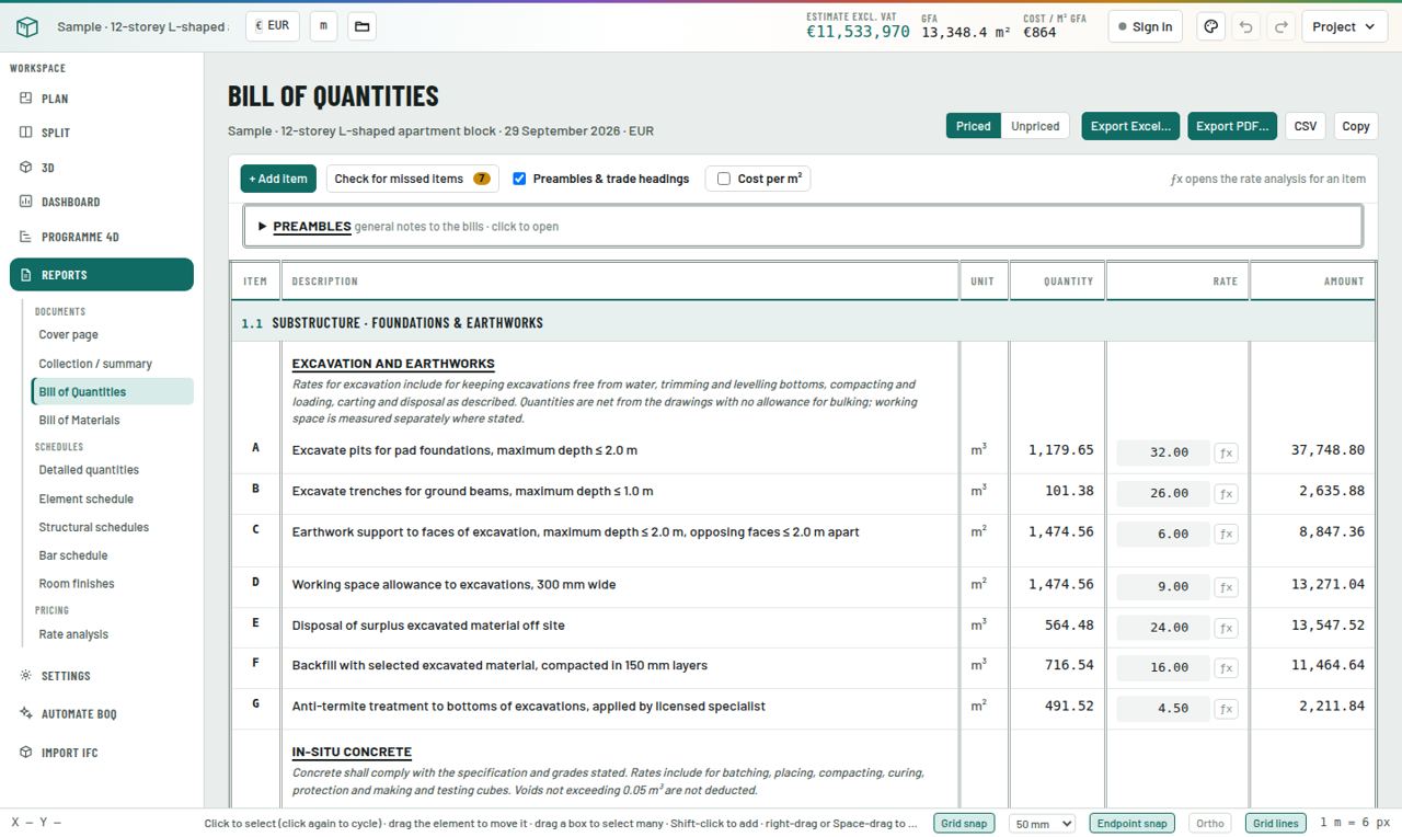
Bill of Quantities to NRM with preambles, trade headings, items, units, quantities, rates and amounts.
Step by step
  1. Open Reports

    Click Reports. Documents: Cover page, Collection / summary, Bill of Quantities, Bill of Materials. Schedules: Detailed quantities, Element schedule, Structural schedules, Bar schedule, Room finishes. Pricing: Rate analysis.

  2. Read the bill

    Items are grouped into NRM sections (1.1 Substructure, 2.5 External walls…) with trade headings and preambles. Each line has item letter, description, unit, quantity, rate and amount.

  3. Priced or unpriced

    Switch between Priced and Unpriced at the top. Send the unpriced bill to tenderers and keep the priced one as your estimate.

  4. Add items

    + Add item adds provisional sums, prime cost sums or anything not modelled. Check for missed items lists typical items your model does not yet include.

  5. Trace a quantity

    Detailed quantities shows the dimension build-up behind every item, element by element, so you can defend any number.

  6. Bar schedule

    Every bar with mark, type, diameter, number, length, shape and weight, plus a summary by diameter and a ratio check (kg/m³).

  7. Bill of Materials

    Converts the measured work into cement bags, sand, aggregate, blocks, steel and more, using your mixes.

  8. Export

    Export Excel gives one workbook with the bill, collection, schedules and materials on separate sheets. Export PDF gives the printed document with cover. CSV and Copy paste straight into other software.

Pro tips
  • Edit cover details and your logo in Settings → Cover & branding before exporting. It is the first page the client sees.
Common mistake
  • Sending the priced bill to tenderers. Always check the Priced/Unpriced switch before exporting.
Exercise

Export Practice House A to Excel. Open it and check the collection totals match the app.

Check yourself · 3 questions
1. Which report shows the dimension build-up behind each item?
2. What does "Check for missed items" do?
3. Which report converts concrete into cement bags?
Level 3 · Report & priceModule 1335 min

Pricing

Turn quantities into a defensible estimate with your own rates.

You will learn
  • Country price database
  • Project data bank
  • Rate analysis build-ups
  • Preliminaries, contingency and VAT
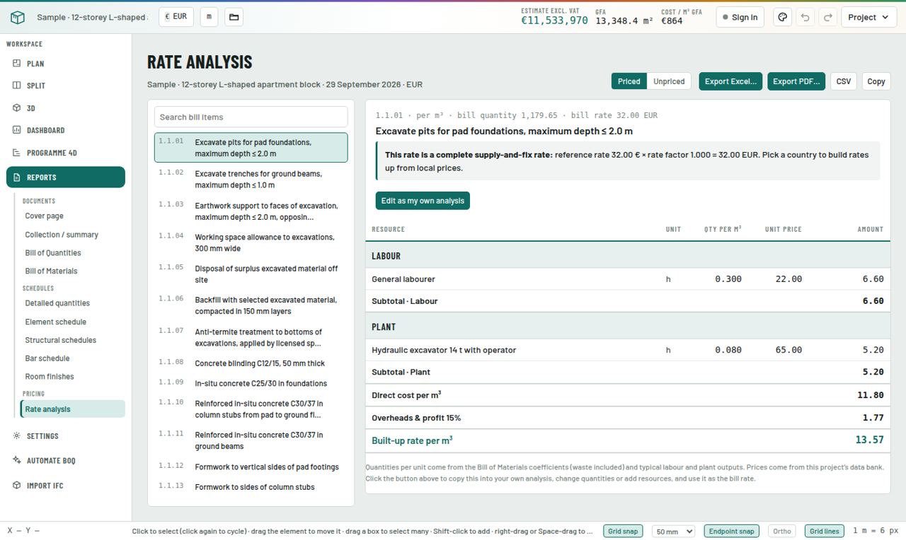
Rate analysis: labour, plant and materials build-up for a single bill item.
Step by step
  1. Country prices

    Settings → Country price database: material, labour and plant prices for the chosen country. Every bill rate is built from these.

  2. Your own rates

    Settings → Data bank (this project): override any resource price for this job, add your own resources, or import a CSV from your company rates.

  3. Rate analysis

    In the bill, click ƒx next to a rate (or open Reports → Rate analysis). Each rate is a build-up of labour hours, plant and materials with wastage, plus overheads and profit. Change any line and the rate updates everywhere.

  4. Global factor

    Settings → Project & currency: a rate factor adjusts every rate at once (for example 1.10 for a remote site).

  5. On-costs

    Settings → Costs & taxes: preliminaries, contingency and VAT appear in the collection and summary.

  6. Present it

    Settings → Cover & branding and Report style: logo, client, consultant, date and document style for the PDF.

Pro tips
  • Change resource prices, not item rates. One cement price change then flows correctly into every concrete, mortar and screed item.
Common mistake
  • Typing a rate straight over the bill without a build-up. It works, but you lose the audit trail.
Exercise

Change the price of cement in the data bank by +10%. Watch how the in-situ concrete, blockwork and plaster rates change.

Check yourself · 3 questions
1. Where do you override a resource price for one project?
2. What does the ƒx button open?
3. Why change resource prices rather than item rates?
Level 3 · Report & priceModule 1425 min

Programme 4D and cash flow

Produce a programme of works and a cash-flow forecast from the same model.

You will learn
  • How the programme is generated
  • Playing the build in 4D
  • Critical path and relationships
  • Exporting to Excel, P6 or MS Project
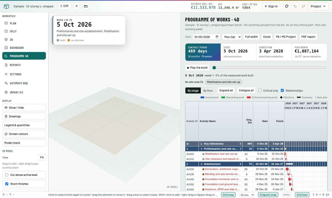
Programme of works in 4D: contract period, start and completion, peak month, and a Gantt chart grouped by stage.
Step by step
  1. Open it

    Click Programme 4D. Every bill line becomes an activity, grouped by stage or by floor, with durations from the quantities and output rates.

  2. Set the calendar

    Enter the start date and working week (for example Mon–Sat). The contract period, completion date and peak month update.

  3. Play the build

    Play the build animates the 3D model week by week. Drag the slider to any date to see what is on site.

  4. Read the Gantt

    Switch By stage or By floor, expand or collapse groups, show Critical only and Relationships.

  5. Cash flow

    The monthly valuation and S-curve come from the priced bill spread over the programme.

  6. Export

    Excel, P6 / MS Project and PDF report.

Pro tips
  • Use the 4D playback in progress meetings. Clients understand a moving model faster than a Gantt chart.
Common mistake
  • Presenting the generated programme as the contractor's programme. It is an estimator's programme for planning and cash flow.
Exercise

Set Practice House A to start next Monday on a Mon–Sat week. Note the completion date and peak month.

Check yourself · 3 questions
1. Where do programme activities come from?
2. Which export suits Primavera?
3. What does "Play the build" show?
Level 4 · HeroModule 1525 min

Automate BOQ and IFC import

Get a first model from drawings or BIM in minutes, then check and finish it.

You will learn
  • Automate BOQ from PDF drawings
  • Using the drawings' own descriptions
  • Importing IFC models
  • Checking automated results
The Bill of Quantities generated from a model. Automated and imported elements are measured in exactly the same way as drawn ones.
Step by step
  1. Automate BOQ

    Click Automate BOQ (you must be signed in on www.agileboq.com). Upload the drawing PDF. The AI reads the plans, sections and notes and builds a first model: levels, grids, walls, columns, beams, slabs, doors, windows, rooms.

  2. Credits

    Each run uses one credit. New accounts get free runs to try it. If a run stops before anything is read, the credit is given back.

  3. Use drawing descriptions

    Turn on Drawing descriptions to use the notes and specifications written on the drawings as the bill descriptions.

  4. Import IFC

    Click Import IFC and drop an IFC file from Revit, ArchiCAD or Tekla. Elements are converted into AgileBOQ elements and measured to NRM. Reinforcement uses your default ratios, which you can edit per element.

  5. Always check

    Treat any automated model as a first draft. Run Model check, compare Legend & quantities with the drawings, and correct sizes and types before issuing.

Pro tips
  • Automate, then refine. The fastest route is AI for the bulk, then your QS judgement for the details.
Common mistake
  • Issuing an automated bill without checking. You are the quantity surveyor; the software is the tool.
Exercise

Import an IFC file you have (or ask a colleague for one), run Model check and list what needed correcting.

Check yourself · 3 questions
1. What should you always do after Automate BOQ?
2. Which BIM format can be imported?
3. What does Drawing descriptions do?
Level 4 · HeroModule 1615 min

Working as a team

Share projects with colleagues and clients safely.

You will learn
  • Inviting people
  • Viewer and editor roles
  • Project files
Team & sharing settings.
Step by step
  1. Invite

    Click Team in the top bar or open Settings → Team & sharing. Enter the person's email and choose a role.

  2. Choose the role

    Can view: opens the model and reports but cannot change anything. Can edit: can model and price. Give clients view-only access.

  3. Send the invitation

    After sharing, AgileBOQ shows a ready-made invitation: send it by email or WhatsApp, or copy it. The person signs in (or creates a free account) with that email and opens the project.

  4. Keep files together

    Settings → Project files keeps specifications, schedules and correspondence with the project.

Pro tips
  • Share the model instead of emailing PDFs back and forth. Everyone always sees the current version.
Common mistake
  • Giving editor access to a client who only needs to look.
Exercise

Share your Practice House A with a colleague as a viewer and ask them to find the total estimate.

Check yourself · 3 questions
1. Which role should a client usually get?
2. How must the invited person open the project?
3. Where are project documents kept?
Capstone2–3 h

Practice House A

Measure a complete single-storey house from its drawing, then compare your bill with the answer key. When your quantities match within 2%, you have the skills this course teaches.

What you get

An A3 ground-floor plan at 1:50: 10 × 8 m, five rooms, 200 mm external and 150 mm internal blockwork, strip footings, ground slab, hipped tiled roof, and a door and window schedule. Dimensions are to wall centrelines.

Open the reference model with Project → Open project file… only after you have finished your own, to compare element by element.

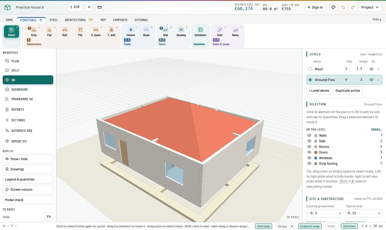
Practice House A in 3D: walls with openings, strip footings and the hipped roof.
The finished reference model.
Your tasks
Answer key · 48 measured items
DescriptionUnitQuantity
1.1 Substructure – foundations & earthworks
Excavate trenches for strip foundations, maximum depth ≤ 2.0 mm³34.5
Earthwork support to faces of excavation, maximum depth ≤ 2.0 m, opposing faces ≤ 2.0 m apartm²115
Working space allowance to excavations, 300 mm widem²115
Disposal of surplus excavated material off sitem³6.9
Backfill with selected excavated material, compacted in 150 mm layersm³27.6
Anti-termite treatment to bottoms of excavations, applied by licensed specialistm²34.5
Concrete blinding C12/15, 50 mm thickm²34.5
In-situ concrete C25/30 in foundationsm³6.9
High-yield bar reinforcement B500B, 10 mm diameter, main bars, straight or bent, in foundationst0.091
High-yield bar reinforcement B500B, 12 mm diameter, main bars, straight or bent, in foundationst0.216
Bitumen damp-proof course 150 mm wide, bedded in mortarm21.5
Bitumen damp-proof course 200 mm wide, bedded in mortarm36
1.2 Substructure – lowest floor construction
Clear site of vegetation, bushes and debris, grub up roots and dispose off site (building footprint plus 1 m all round)m²120
Excavate topsoil average 150 mm deep and remove from sitem²80
Imported murram or granular fill to make up levels to underside of hardcore, compacted in 150 mm layersm³8
Hardcore bed 200 mm thick, compacted, blinded with 50 mm sandm²80
Anti-termite treatment to surface of hardcore under ground slab, applied by licensed specialistm²80
In-situ concrete C25/30 ground-bearing slab 150 mm thickm³12
Formwork to edges of ground slabm36
A142 steel fabric reinforcement, 200 mm lapsm²80
Polythene damp-proof membrane 1200 gauge, lapped and sealedm²80
2.3 Roof
Concrete interlocking roof tiles on battens and breather membrane, pitch 25° (measured on slope)m²88.27
Prefabricated treated timber Fink roof trusses, span 8.00 m, pitch 25°, at 600 mm centres, with galvanised nail plates; hoist and fix to wall platesnr3
Girder roof trusses, 2-ply, span 8.00 m, pitch 25°, at hip ends, including truss hangers and boltsnr2
Half-round ridge tiles, bedded and pointedm2
Half-round hip tiles, bedded and pointed, with hip ironsm23.83
Treated cypress fascia board 225 × 25 mm, primed and paintedm36
Hip jack (mono) trusses, span up to 3.70 m, pitch 25°, fixed with galvanised hangersnr48
Truss bracing: 100 × 25 mm treated timber diagonal, longitudinal and chevron bracing, nailed to every trussm25.6
Galvanised truss clips / hurricane straps fixing trusses to the wall platenr58
Sawn treated cypress 100 × 50 mm wall plate, bedded and fixed with hoop iron strapsm36
PVC-U eaves gutter 125 mm, including brackets and outletsm36
2.5 External walls
Hollow concrete blockwork 200 mm thick in cement mortar (1:4)m²94.95
Precast concrete lintel 200 mm wide × 150 mm deep, 150 mm bearing each endm12.9
2.6 Windows and external doors
Aluminium casement window 600 × 600 mm, double glazed, including sill, fixings and sealantnr1
Aluminium casement window 1500 × 1200 mm, double glazed, including sill, fixings and sealantnr6
External door set 900 × 2100 mm, solid hardwood leaf and frame, threshold, security ironmongery, decorationnr1
2.7 Internal walls and partitions
Hollow concrete blockwork 150 mm thick in cement mortar (1:4)m²57.78
Precast concrete lintel 150 mm wide × 150 mm deep, 150 mm bearing each endm4.4
2.8 Internal doors
Internal door set 800 × 2100 mm, flush leaf, hardwood frame and architraves, ironmongery, decorationnr4
3.1 Wall finishes
12 mm cement–sand plaster (1:4) to internal wall facesm²200.52
15 mm two-coat cement–sand render (1:4) to external wallsm²94.95
Emulsion paint, mist + two full coats, to plastered wallsm²200.52
Masonry paint, two coats, to rendered external wallsm²94.95
3.2 Floor finishes
Cement–sand screed (1:3) 50 mm thick to floorsm²73.32
Ceramic floor tiles 600 × 600 mm on adhesive, groutedm²73.32
Skirting 100 mm high to match ceramic tilesm68.25
3.3 Ceiling finishes
Suspended gypsum plasterboard ceiling 12.5 mm on metal grid, skim and paintm²73.32

Quantities from the reference model with default settings. Differences of up to 2% come from how corners and openings are traced. Bigger differences usually mean a wrong wall type, a missing opening, the roof on the wrong level, or a scale error.

Hero challenge

Turn Practice House A into a two-storey house: add a 150 mm suspended slab on the Ground Floor walls, use Duplicate active to create the first floor, move the roof up one level, and add a straight staircase in the living room with a slab opening above it. Then price it, set a programme starting next Monday, and present the Dashboard in three minutes.

Shortcut card

Keep this next to your screen for the first week.

VSelect / move
LStructural grid line
MMeasure distance
KCalibrate scale
FStrip footing
PPad footing
GGround beam
UFoundation wall
CColumn
BBeam
SSlab
OSlab opening
IStaircase
JRamp
WWall
QCurtain wall
DDoor
NWindow
ZLouvre
TRoof
YBalustrade
RRoom
ASanitary fitting
EPipe run
XValve / fitting
HManhole
EnterClose polygon / place typed length
EscFinish chain / cancel
ShiftOrtho while drawing
DelDelete selection
Ctrl+ASelect all visible
Ctrl+Z / Ctrl+YUndo / redo
HomeZoom to fit

For trainers

The course runs as a two-day classroom or online workshop. Each trainee needs a laptop, a modern browser and a free AgileBOQ account.

SessionModulesActivity
Day 1 · morningModules 1–4Tour, projects, settings, drawings. Everyone imports and calibrates the practice drawing.
Day 1 · afternoonModules 5–8Drawing tools, substructure, frame and architecture. Trainees model Practice House A walls, footings, openings and roof.
Day 2 · morningModules 9–12MEP, composite items, model check, reports. Trainees finish the capstone and compare with the answer key.
Day 2 · afternoonModules 13–16Pricing, programme, automation, teamwork. Hero challenge, then each trainee presents their dashboard in 3 minutes.

Assessment: the capstone bill within 2% of the answer key on every measured line, all module quizzes passed, and a three-minute dashboard presentation.